This website is a participant in the Amazon Services LLC Associates Program, an affiliate advertising program designed to provide a means for us to earn fees by linking to Amazon.com and affiliated sites.
In orthographic projection, the projectors are parallel and perpendicular (at a 90-degree angle) to the plane of projection. This fundamental rule is the core of creating accurate, scaled engineering and technical drawings. Understanding this principle is essential for clear communication in design and manufacturing.
This precise method eliminates perspective distortion, allowing exact measurements to be taken directly from the drawing. It solves the problem of representing a 3D object in 2D without size or shape alteration. This is critical for producing reliable blueprints and plans.
This complete guide will explain the projector orientation, its importance, and how it creates standard views. You will learn expert tips for visualizing projections and the proven methods used across industries. Master this foundational concept to excel in technical drawing.
Best Drafting Tools for Mastering Orthographic Projection
Creating precise orthographic projections requires reliable tools. The right equipment ensures accuracy, clarity, and professional results. Here are three top-rated products recommended for students, engineers, and drafters to execute perfect parallel projections with ease.
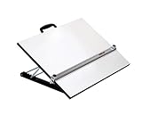
Alvin Drafting DMS Portable Drafting Board – Best Overall Choice
This portable board provides a stable, parallel-ruled surface ideal for manual orthographic drawing. Its aluminum parallel straightedge glides smoothly, guaranteeing projectors are perfectly parallel to your paper plane. It’s the best option for students and professionals needing a reliable, traditional setup for accurate multi-view drawings.

- A PROFESSIONAL’S CHOICE – Alvin has been the professional’s choice for drafting tools and drawing supplies for over half a century. Since 1950, we have brought…
- SUPERB QUALITY – Fully assembled and equipped with features that would help you create an accurate drawings and drafts; white, aluminum straightedge, acrylic blade…
STAEDTLER Mars 568 Technical Drawing Set – Premium Instrument Kit
This comprehensive set includes compasses, dividers, and ruling pens for impeccable line work. The high-precision German engineering ensures every line drawn is consistent and sharp, which is critical for depicting perpendicular projectors clearly. Ideal for detailed architectural or mechanical projection work requiring utmost precision.
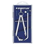
- PROFESSIONAL DESIGN – Metal build, a comfort grip, and interchangeable leads provide durability for technical drawings. Used by architects, engineers, and artists…
- PRECISE DRAWING – Features a comfort grip on top and micro-step adjustment wheel to lock in the exact diameter you need. Draws circles up to 10.5″ on its own, up to…
Mayline 12230-SS Wood Parallel Straightedge – Professional Studio Standard
A durable, wall-mounted straightedge system for large-format drafting tables. Its counterbalanced design and stainless steel cable provide flawless horizontal line drawing, directly supporting the core principle of parallel projection. This is the recommended permanent solution for studios and classrooms dedicated to technical drawing.
- The only parallel straightedge board utilizing an anti-warp aluminum body straightedge for strength and stability
- Equipped with a five-position adjustable stand to create a 10 to 45 degree angle
Understanding the Core Principle: Parallel and Perpendicular Projectors
Orthographic projection is defined by the specific orientation of its imaginary sight lines, called projectors. This orientation is the non-negotiable rule that creates its unique, measurable views. Grasping this concept is the first step to mastering technical drawing.
What Are Projectors in Technical Drawing?
In drafting, projectors are imaginary lines of sight that extend from the object to the drawing surface. They represent how the viewer’s eye sees every point on the object. In perspective drawing, these lines converge; in orthographic, they follow a strict parallel path.
- Visualization Tool: They are a conceptual framework, not physically drawn on the final blueprint.
- Path of Points: Each vertex or feature on the 3D object travels along a projector line to its 2D position.
- Defining Characteristic: The behavior of these lines categorizes the type of projection used.
The Exact Orientation: “Parallel and Perpendicular” Explained
The complete answer to the statement is: projectors are both parallel to each other and perpendicular to the plane of projection. This dual condition is critical for accuracy.
First, all projectors run perfectly parallel, never converging. Second, they strike the drawing plane at a consistent 90-degree angle. This eliminates any foreshortening or perspective distortion seen in artistic drawings.
Why This Orientation Creates True Shape and Size
Because the sight lines are parallel and perpendicular, dimensions are preserved. A 100mm line on the object is drawn as 100mm on the view where it is parallel to the plane. This allows for direct scaling and measurement.
This principle enables the standard multiview projection layout (front, top, side). Each view is created by looking directly at one face, with projectors perpendicular to it. The result is a set of flat, true-shape representations essential for manufacturing.
How Orthographic Projection Differs from Other Drawing Methods
Understanding what makes orthographic projection unique requires comparison. Its strict projector rule creates a distinct advantage over other common drawing systems. This section contrasts it with perspective and axonometric projections.
Orthographic vs. Perspective Projection: A Clear Distinction
The key difference lies in projector behavior. In perspective, projectors converge at a station point (the viewer’s eye). This creates realistic depth but distorts true dimensions.
- Projector Path: Orthographic uses parallel lines; perspective uses converging lines.
- Size Accuracy: Orthographic preserves true size; perspective foreshortens distant objects.
- Primary Use: Orthographic is for technical fabrication; perspective is for visual realism.
Comparison with Other Parallel Projections: Isometric and Oblique
Isometric and oblique drawings are also parallel projections, but with a different plane orientation. Their projectors are parallel but not perpendicular to the picture plane. This shows three faces at once but with slightly distorted shapes.
| Projection Type | Projector Angle to Plane | Key Characteristic | Best For |
|---|---|---|---|
| Orthographic | 90° (Perpendicular) | True shape & size of one face | Manufacturing dimensions |
| Isometric | Not 90° (Tilted) | 3D appearance with parallel lines | Conceptual assembly diagrams |
| Perspective | Converging (Various) | Realistic visual depth | Architectural renderings |
The Critical Advantage for Engineering and Manufacturing
The perpendicular projector rule enables direct measurement. A machinist can take dimensions straight from the orthographic view to the raw material. This eliminates guesswork and calculation errors.
This makes it the universal language for engineering drawings. A front, top, and side view provide all necessary information to manufacture a part anywhere in the world. Consistency is guaranteed by the strict parallel and perpendicular standard.
Practical Applications and Creating Orthographic Views
The theory of parallel projectors is applied to create standard multiview drawings. This process translates a three-dimensional object into a set of two-dimensional blueprints. Mastering this application is essential for any technical field.
Step-by-Step Process for Generating Standard Views
Creating an orthographic projection follows a logical sequence. It begins by positioning the object in a glass box, with each face touching an interior plane.
- Position the Object: Orient the object so its principal faces are parallel to the sides of an imaginary glass box.
- Project Perpendicularly: From each feature (vertex, edge), imagine projectors extending perpendicularly to each of the six box planes.
- Unfold the Box: Conceptually unfold the glass box to lay all six views flat on a single drawing sheet, maintaining alignment.
Real-World Examples in Industry
This method is not academic; it is the backbone of industrial design and production. Its precision drives manufacturing and construction worldwide.
- Mechanical Engineering: Every machined part, from a simple bolt to a complex engine block, is defined by orthographic drawings for CNC programming.
- Architecture: Building plans (floor plans, elevations) are orthographic projections, showing true wall lengths and window openings.
- Patent Drawings: Legal patents require orthographic views to unambiguously define an invention’s scope and design.
Common Mistakes and How to Avoid Them
Errors occur when the fundamental rule of parallel, perpendicular projectors is broken. Awareness of these pitfalls improves drawing accuracy significantly.
A frequent error is misaligned features between views. This happens when projectors are not kept perfectly perpendicular and parallel. Use a 45° miter line to correctly transfer depth dimensions between the top and side views.
Another mistake is incorrect line precedence where hidden lines obscure visible edges. Always prioritize visible object lines over hidden ones to maintain drawing clarity and avoid misinterpretation on the shop floor.
Modern Tools and the Future of Orthographic Drawing
The core principle of parallel projection remains unchanged, but the tools have evolved dramatically. Today, software automates the rigorous process while still adhering to the fundamental rules. Understanding this digital transition is key for modern drafters.
From Manual Drafting Boards to CAD Software
Computer-Aided Design (CAD) has revolutionized technical drawing. Programs like AutoCAD, SolidWorks, and Fusion 360 have internalized the rules of orthographic projection.
- Automated Projection: The user creates a 3D model, and the software automatically generates perfectly aligned multiview drawings with parallel, perpendicular projectors.
- Dynamic Updates: Changing the 3D model instantly updates all associated orthographic views, ensuring consistency and saving immense time.
- Precision Guarantee: Digital tools eliminate human error in maintaining parallel lines and right angles, enforcing the standard with mathematical precision.
How CAD Enforces the “Parallel and Perpendicular” Rule
In a CAD environment, the projector concept is embedded in the view generation engine. When you command a “Base View” or “Drawing View,” the software calculates the projection mathematically.
It treats the screen or drawing sheet as the plane of projection. The software then generates lines of sight from the 3D model that are perfectly parallel and strike that plane at 90 degrees. This digital process guarantees ISO and ANSI standard compliance.
| Aspect | Manual Drafting | CAD Software |
|---|---|---|
| Projector Creation | Imagined/guided by drafter’s skill & tools | Automated by software algorithm |
| View Alignment | Manual use of T-square & triangles | Automatic, parametric alignment |
| Error Correction | Time-consuming erasing & redrawing | Instant update from 3D model edit |
The Enduring Relevance of the Fundamental Principle
Despite advanced 3D modeling and augmented reality, orthographic drawings are irreplaceable. Manufacturing machines, quality control checks, and assembly instructions rely on 2D dimensioned views.
The principle of parallel projectors perpendicular to the plane ensures these documents are unambiguous. As long as physical objects are built, this centuries-old rule will remain the cornerstone of technical communication.
Mastering Orthographic Projection: Expert Tips and Best Practices
Applying the theory correctly leads to professional, error-free drawings. These actionable strategies will help you internalize the concept of parallel projectors and produce superior technical documentation. Implement these tips to enhance your drafting accuracy and efficiency.
Visualization Techniques for Accurate Projection
Developing strong spatial reasoning is crucial. You must mentally rotate objects and trace the path of perpendicular projectors.
- Use the “Glass Box” Method: Always mentally enclose your object in a transparent box. Visualize the object’s features touching the six interior planes to establish your principal views.
- Practice with Simple Solids: Start with basic shapes like cubes, cylinders, and pyramids. Sketch their front, top, and side views manually to build foundational skills before using CAD.
- Trace Projector Paths: For a complex point, physically trace with your finger or pencil from the point straight across to the adjacent view, enforcing the perpendicular path concept.
Ensuring Precision in Manual and Digital Drafting
Precision is non-negotiable. Whether using a board or software, your process must enforce the parallel rule.
- Start with Construction Lines: Use light, fine lines to map out the alignment and projection paths between views before committing to final object lines.
- Leverage CAD Constraints: In software, use “Vertical” and “Horizontal” geometric constraints to force lines to be parallel to the axes, mirroring the perpendicular projector rule.
- Validate with the 45° Miter Line: For manual drafting, use a 45° line to accurately transfer depth dimensions between the top and right-side view, maintaining proportional accuracy.
Key Standards and Conventions to Follow
Orthographic projection is governed by international standards to ensure universal understanding. Adhering to these is as important as the geometric principle itself.
Familiarize yourself with ASME Y14.3 or ISO 128 standards. These dictate view placement (first-angle or third-angle projection), line types, and dimensioning practices. Consistent use of correct, standardized hidden lines (dashes) and center lines is critical for clear communication across global teams.
Frequently Asked Questions About Orthographic Projection
This section addresses common points of confusion and specific queries related to projector orientation. Clear answers reinforce the core concepts and provide quick reference for readers. These FAQs are structured to target common long-tail search queries.
What is the Primary Purpose of Using Orthographic Projection?
The primary purpose is to create dimensionally accurate, true-shape representations of an object for manufacturing or construction. It allows precise measurements to be taken directly from the 2D drawing.
This eliminates the guesswork and distortion found in pictorial drawings. It serves as a universal technical language between designers, engineers, and machinists, ensuring a part is built exactly as intended.
First-Angle vs. Third-Angle: Does the Projector Rule Change?
No, the fundamental rule does not change. In both systems, projectors remain parallel and perpendicular to the plane of projection. The difference lies only in the arrangement of the views on the drawing sheet.
- Third-Angle Projection (US Standard): The view is placed on the side of the plane opposite the direction of sight. Imagine the view being projected onto a plane behind the object.
- First-Angle Projection (ISO Standard): The view is placed on the side of the plane facing the direction of sight. Imagine the view being projected onto a plane in front of the object.
Can You Have an Orthographic View That is Not a Principal View?
Yes. While front, top, and side are principal (standard) views, orthographic projection can create a view from any direction, as long as the projectors are parallel and perpendicular to that new plane.
These are called auxiliary views. They are used to show the true shape and size of an inclined or oblique surface that is foreshortened in the principal views. The projector rule is strictly maintained to project onto this auxiliary, tilted plane.
Conclusion and Final Summary of Key Concepts
Mastering orthographic projection is foundational for success in engineering, architecture, and design. This guide has detailed the core principle, its applications, and modern practices. Let’s consolidate the essential takeaways to ensure you can confidently apply this knowledge.
Recap: The Definitive Answer to the Core Question
To state it definitively: In orthographic projection, the projectors are parallel to each other and perpendicular (at a 90° angle) to the plane of projection. This is the non-negotiable geometric rule that defines the entire system.
This specific orientation is what creates measurable, true-shape views. It distinguishes orthographic from all other projection methods, making it the indispensable language of technical drawing and manufacturing.
The Enduring Importance of This Foundational Skill
Despite the rise of 3D modeling and immersive visualization, the orthographic drawing remains the legal and practical document for fabrication. It translates creative design into executable instructions.
- Universal Communication: It provides an unambiguous standard understood globally, regardless of language barriers.
- Precision Manufacturing: It delivers the exact dimensions and tolerances required for CNC machining, welding, and assembly.
- Problem-Solving Framework: The mental discipline of multiview visualization is critical for design thinking and spatial reasoning.
Your Next Steps for Mastery
Begin applying this knowledge immediately. Start by sketching orthographic views of simple household objects. Then, progress to using CAD software to create 3D models and generate automatic multiview drawings.
Continuously compare the software’s output with the underlying theory. This practice will solidify your understanding and make you a proficient, versatile drafter and designer, capable of bridging the gap between concept and physical reality.
Orthographic projection provides the unambiguous precision needed to turn ideas into real objects. Its rule of parallel, perpendicular projectors guarantees measurable, true-shape views for manufacturing.
The key takeaway is mastering this foundational principle. It applies equally to manual drafting and modern CAD software.
Start practicing by sketching multiviews of simple items around you. Then, explore creating them in a CAD program.
You now possess the core knowledge to create professional technical drawings. Use it to communicate your designs with perfect clarity.
Frequently Asked Questions about Orthographic Projection
What is the main advantage of orthographic projection over perspective drawing?
The main advantage is dimensional accuracy and true-shape representation. You can take direct measurements from the drawing for manufacturing. This eliminates the distortion and foreshortening inherent in perspective views.
This makes it the essential standard for engineering blueprints and construction plans. It ensures a part is built to exact specifications, which is critical for functionality and assembly.
How do you draw an orthographic projection from an isometric view?
First, identify the principal faces (front, top, side) visible in the isometric. Then, visualize or draw construction lines projecting perpendicularly from each key point on the isometric to an imaginary plane.
These projectors must be parallel. Transfer the projected points to create separate, aligned 2D views. This process manually enforces the core rule of parallel, perpendicular projection lines.
Why are hidden lines important in an orthographic drawing?
Hidden lines (dashed) show interior features or edges that are not visible in that particular view. They provide complete information about the object’s internal geometry and depth.
This prevents misinterpretation and ensures the manufacturer understands the full shape. Following standard line conventions (ASME Y14.2) for hidden lines is crucial for clear communication.
What is the difference between first-angle and third-angle projection symbols?
The symbols indicate how the views are arranged on the drawing sheet. The third-angle symbol shows a side view of a cone placed to the right of the front view. The first-angle symbol shows it to the left.
You must check the title block for this symbol. Using the wrong standard can cause catastrophic misinterpretation, as views are mirrored. The USA primarily uses third-angle; Europe uses first-angle.
How does CAD software automatically create orthographic views?
CAD software uses the 3D model’s mathematical data. When you place a base view, the software calculates a view direction and then projects all model geometry onto a 2D plane using perfectly parallel, perpendicular virtual projectors.
It automates alignment and scaling. The software strictly adheres to the orthographic rule, ensuring generated views are always dimensionally accurate projections of the 3D model.
What is an auxiliary view in orthographic projection?
An auxiliary view is an orthographic view projected onto a plane that is not parallel to the principal planes (front, top, side). It is used to show the true shape and size of an inclined surface.
The projectors remain perpendicular to this new, auxiliary plane. This specialized view is essential for dimensioning features that appear foreshortened in the standard principal views.
What are the most common mistakes students make with orthographic projection?
Common mistakes include misaligned views, incorrect line precedence (hidden over visible), and forgetting to project features between views. These errors break the rule of parallel projection.
Another error is improper spacing between views. Using construction lines and a 45° miter line for depth transfer helps avoid these issues and maintains drawing accuracy.
What is the best way to practice and improve orthographic visualization skills?
The best way is consistent, hands-on practice. Start by sketching the three standard views of simple physical objects, like a book or a mug. Use the “glass box” method to mentally enclose the object.
Then, progress to more complex assemblies and practice converting between 3D pictorial sketches and 2D multiview drawings. This builds the spatial reasoning essential for all technical design work.
Can You Use a Projector Without a Laptop? why you need to know
This website is a participant in the Amazon Services LLC Associates Program, an affiliate advertising program designed to provide a means for us to earn fees by linking to Amazon.com and affiliated sites.